I. Core Principles of Variable Reluctance Resolvers
First, to understand the design, one must understand its fundamental differences from traditional wound-rotor resolvers:
· Traditional Resolver:
Both stator and rotor have windings. The excitation signal and output signal are electromagnetically induced across the air gap.
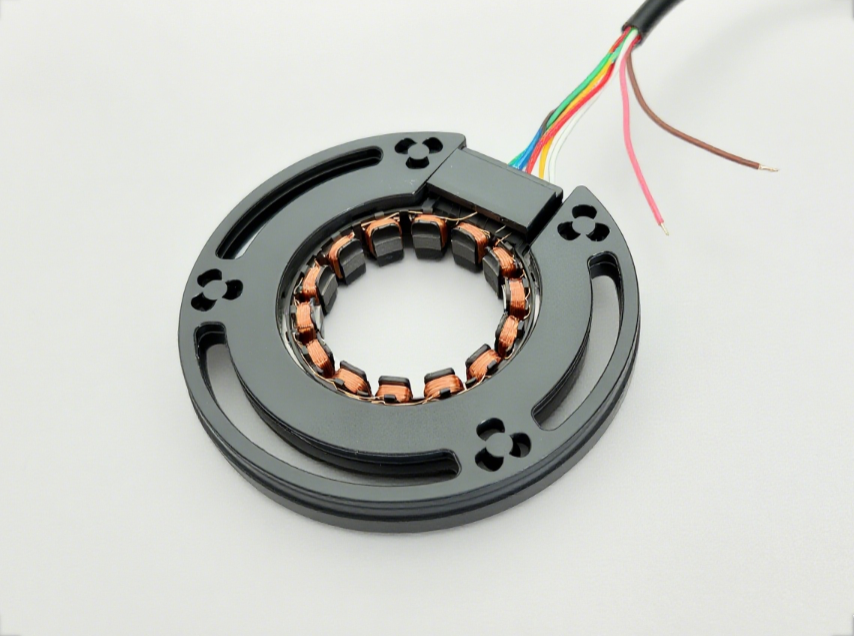
· Variable Reluctance (VR) Resolver:
Only the stator has windings. The rotor is a
non-wound ferromagnetic component made of salient poles or a toothed structure. Its working principle is based on
reluctance variation.
o Stator Windings:
Typically include one excitation winding (primary) and two output windings (sine and cosine windings, secondary) that are spatially orthogonal (90 electrical degrees apart).
o Rotor Rotation:
When the rotor with salient poles rotates, it changes the air gap length and the reluctance of the magnetic circuit.
o Signal Modulation:
The variation in air gap reluctance modulates (amplitude modulation) the voltage amplitude induced in the output windings by the excitation magnetic field. The amplitude envelopes of the two output windings are sinusoidal and cosine functions of the rotor angle, respectively.
Its advantages are: simple structure, rugged and durable (brushless), low cost, high reliability, ability to withstand high-speed and high-temperature environments. The disadvantage is that accuracy and linearity are usually slightly lower than those of high-precision wound-rotor resolvers.
II. Design Process and Key Considerations
The design process is iterative and typically follows these steps:
1. Define Design Specifications
This is the starting point for all designs and must be clarified first:
· Number of Pole Pairs (P):
Determines the relationship between electrical and mechanical angles (θ_electric = P * θ_mechanical). Common configurations are 1 pole pair (unipolar) and 2 pole pairs (bipolar). The number of pole pairs affects accuracy and maximum speed.
· Accuracy Requirements:
Usually expressed in arcminutes (′) or milliradians (mrad). High-precision designs require extremely high demands on manufacturing, materials, and magnetic field harmonic suppression.
· Input Excitation Signal:
Excitation voltage amplitude, frequency (common ones are 4kHz, 10kHz, etc.), waveform (usually sinusoidal).
· Transformation Ratio (TR):
The ratio of output voltage to input voltage (at the position of maximum coupling).
· Electrical Error:
Includes function error, null voltage error, phase error, etc.
· Operating Environment:
Temperature range, vibration, shock, humidity, ingress protection (IP) rating.
· Size Constraints:
Outer diameter, inner bore, thickness (length).
· Impedance Parameters:
Input/output impedance, affecting matching with subsequent circuitry.
2. Electromagnetic Design - Core Part
· Stator/Rotor Lamination Design:
o Material Selection:
Typically uses silicon steel sheets with high permeability and low iron loss (e.g., DW540, 50JN400).
o Pole-Slot Combination:
This is the soul of the design. The number of stator slots (Zs) and rotor salient poles (Zr) must be determined. The most common combination is
Zr = 2P (number of rotor poles equals twice the number of pole pairs), and Zs is a multiple of Zr. For example, a unipolar resolver (P=1) often uses
Zs=4, Zr=2; a bipolar resolver (P=2) often uses
Zs=8, Zr=4 or
Zs=12, Zr=6.
o Slot/Pole Shape:
The shape of the teeth (parallel, tapered) affects magnetic field distribution and harmonic content. Dimensions such as tooth width, slot opening width, and yoke thickness need optimization to maximize fundamental magneto-motive force (MMF) and minimize slot harmonics.
o Air Gap:
The air gap size is a critical trade-off. A small air gap increases the transformation ratio and signal strength but increases manufacturing difficulty, sensitivity to eccentricity, and torque ripple. A large air gap has the opposite effect. Typically designed between 0.05mm - 0.25mm.
· Winding Design:
o Type:
Typically distributed windings or concentrated (tooth) windings are used. Distributed windings (one coil spanning multiple slots) produce a more sinusoidal magnetic field but are more complex to manufacture; concentrated windings are simpler but have higher harmonics.
o Turn Calculation:
Based on the target transformation ratio, excitation voltage, and frequency, determine the number of turns for the excitation winding and the sine/cosine windings through electromagnetic calculation. The number of turns for the two output windings must be strictly identical.
o Connection Method:
Ensure the sine and cosine windings are strictly 90 electrical degrees apart spatially.
3. Magnetic Field Simulation and Optimization (FEA Simulation) - Essential Modern Design Tool
Purely analytical calculations are very complex and insufficiently accurate. Finite Element Analysis (FEA) software (e.g., JMAG, ANSYS Maxwell, Simcenter Magnet) is essential.
· Static Field Simulation:
Calculate magnetic field distribution, inductance matrix, and output potential at different rotor angles.
· Transient Field Simulation:
Apply the actual excitation voltage to simulate the output voltage waveform, more accurately reflecting performance.
· Parametric Optimization:
Perform parametric sweeps and optimization of key dimensions like tooth shape, air gap, and slot opening to minimize error (e.g., THD) and maximize the transformation ratio.
· Error Analysis:
Calculate electrical error through simulation and analyze error sources (e.g., harmonics, cogging effect, saturation effect).
4. Mechanical Structure Design
· Housing and Bearings:
Design the support structure and select appropriate bearings to ensure concentricity between rotor and stator and minimal air gap variation, while withstanding specified vibration and shock.
· Shaft Connection:
Design keyways, smooth bore, or servo interface to ensure reliable connection and backlash-free transmission with the motor shaft.
· Thermal Management:
Consider heat generation from windings and iron losses to prevent overheating in high-temperature environments. Thermal path design is sometimes necessary.
· Electromagnetic Shielding:
Add a shield if necessary to prevent interference from external magnetic fields.
5. Signal Processing Circuit Considerations
Although not part of the resolver body design, it must be considered synergistically:
· RDC (Resolver-to-Digital Converter):
Select an RDC chip (e.g., AD2S1205, AU6802) that matches the resolver's impedance and excitation frequency. Input impedance matching is required during design.
· Excitation Drive Circuit:
Requires a power op-amp circuit capable of providing a clean, stable sine wave.
· Filter Circuit:
Filter the output signals to suppress high-frequency noise and harmonics.
III. Design Challenges and Key Technologies
1. Harmonic Suppression:
Due to the non-linearity of its reluctance variation, the output voltage of a VR resolver contains rich harmonics, which are the main cause of error. Methods like
pole-slot combination optimization, skewing (slots or poles), and adding auxiliary slots on stator teeth can effectively suppress harmonics.
2. Balancing Accuracy and Cost:
High accuracy implies more precise machining (smaller air gap, higher concentricity), higher quality materials (higher grade silicon steel), more complex designs (e.g., more pole pairs, fractional slots), and stricter processes, leading to sharply increasing costs.
3. Temperature Drift:
The resistance of windings and the properties of silicon steel change with temperature, causing amplitude and phase drift. Compensation in the circuit or software is needed, or materials with good temperature stability should be selected during electromagnetic design.
Summary
Design Recommendations:
1. Start with Specifications:
First, thoroughly understand the specific requirements of your application scenario regarding accuracy, size, and environment.
2. Leverage Proven Solutions:
Start with classic pole-slot combinations (e.g., 4-2, 8-4), as they are a verified and reliable starting point.
3. Simulation-Driven Design:
Don't stop at theoretical calculations; immediately use FEM software to create a parametric model for simulation and optimization. This is key to improving design success rates and shortening development cycles.
4. Iterate and Test:
After building a prototype, conduct comprehensive performance tests (error, temperature rise, vibration, etc.), compare with simulation results, analyze the causes of differences, and proceed to the next design iteration.
5. Think at the System Level:
Consider and debug the resolver sensor and the downstream RDC circuit as an integrated system.
The design of variable reluctance resolvers is a highly practical technology that requires repeated cycles of theory, simulation, and experimentation.


